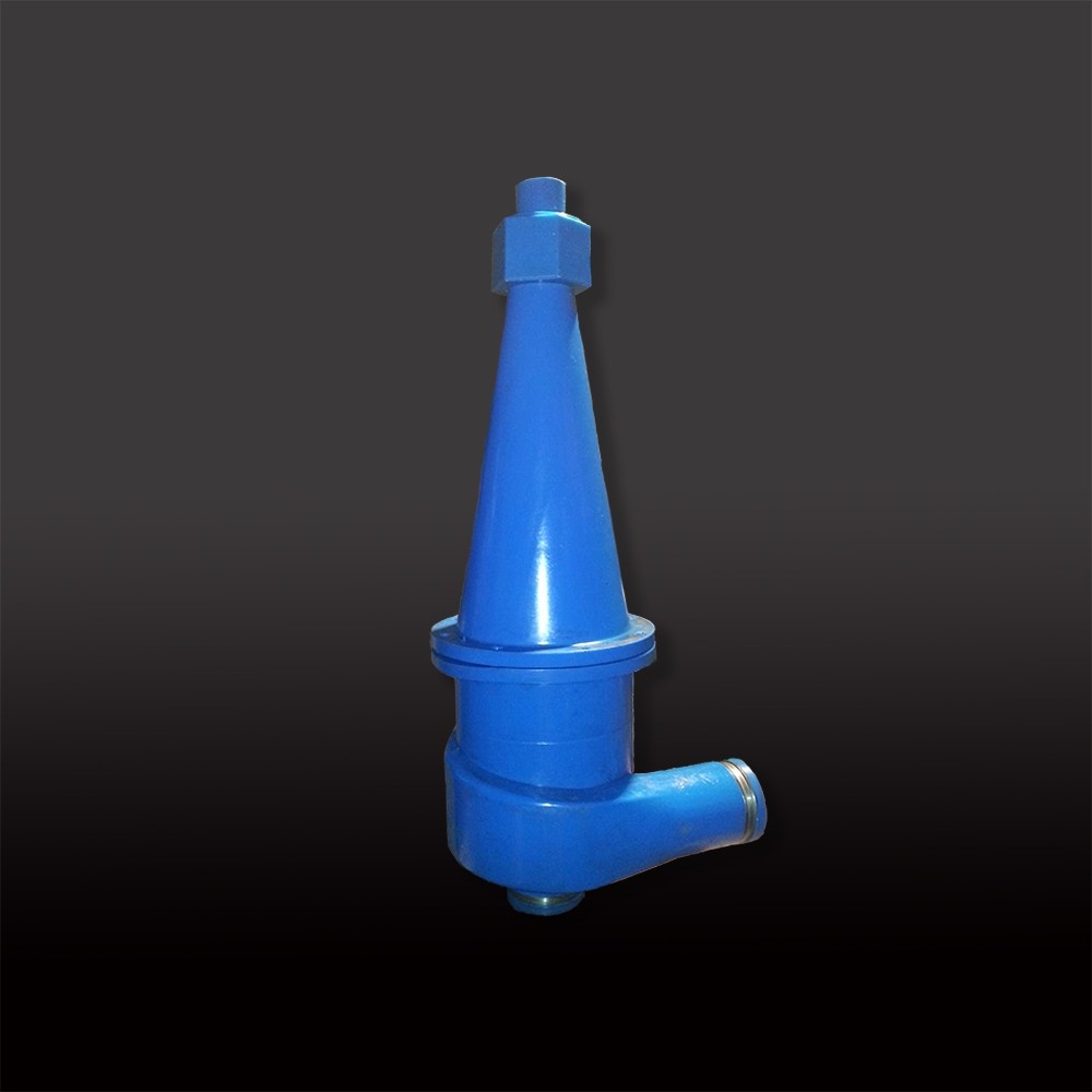
Hydrocyclone
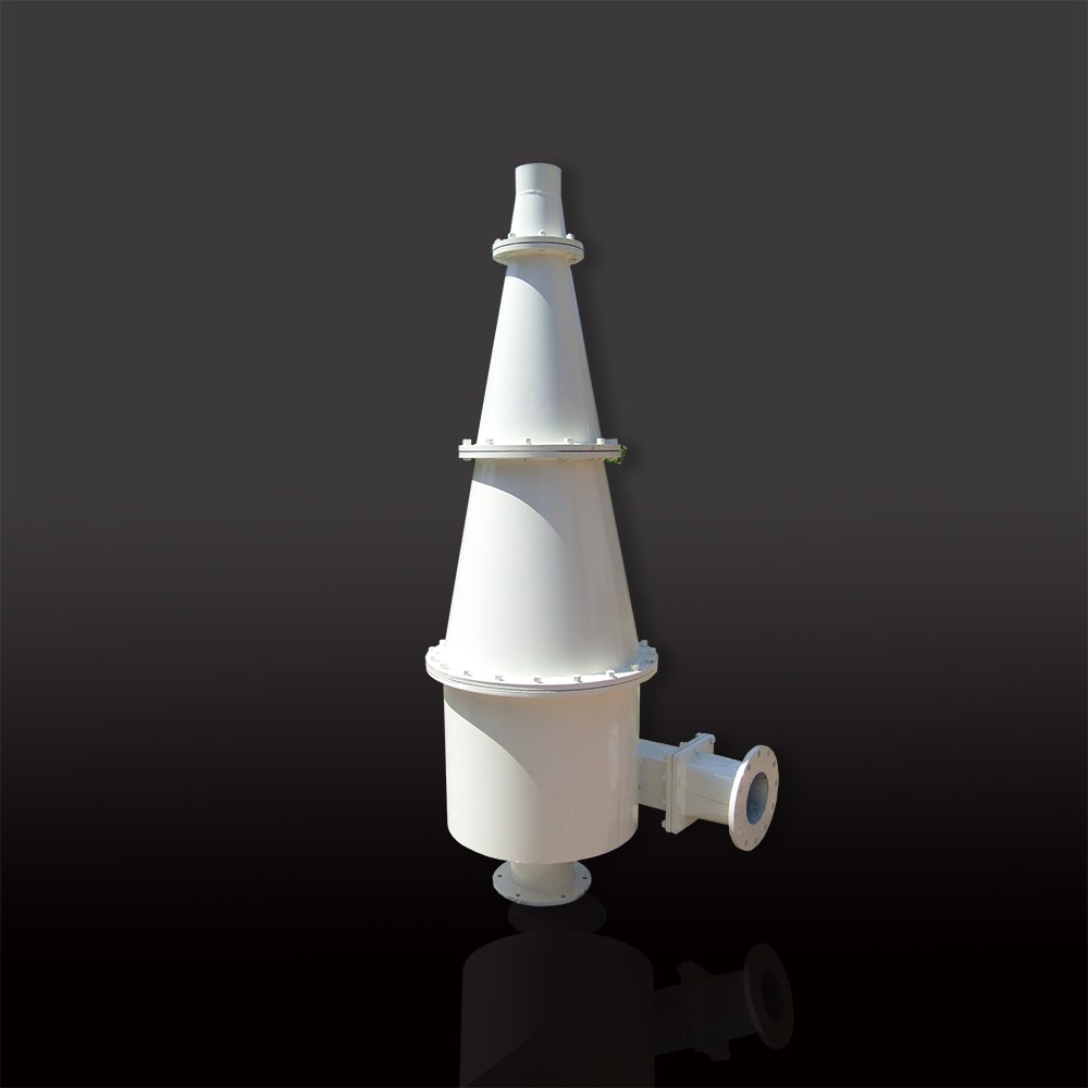
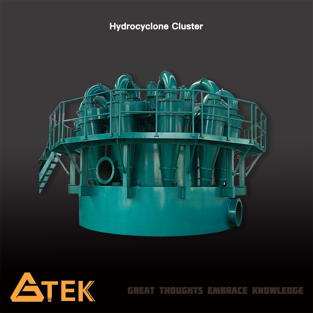
Hydrocyclone is a continuously device that utilizes centrifugal force to accelerate the settling rate of particles. GTEK FX Series Hydrocyclones have a metal shell and optional lining of ceramic and rubber.
Description
Hydrocyclone is a continuously device that utilizes centrifugal force to accelerate the settling rate of particles. GTEK FX Series Hydrocyclones have a metal shell and optional lining of ceramic and rubber.
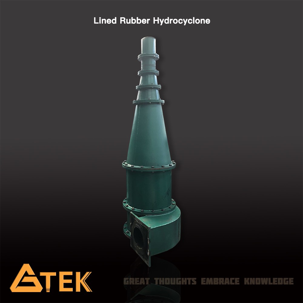
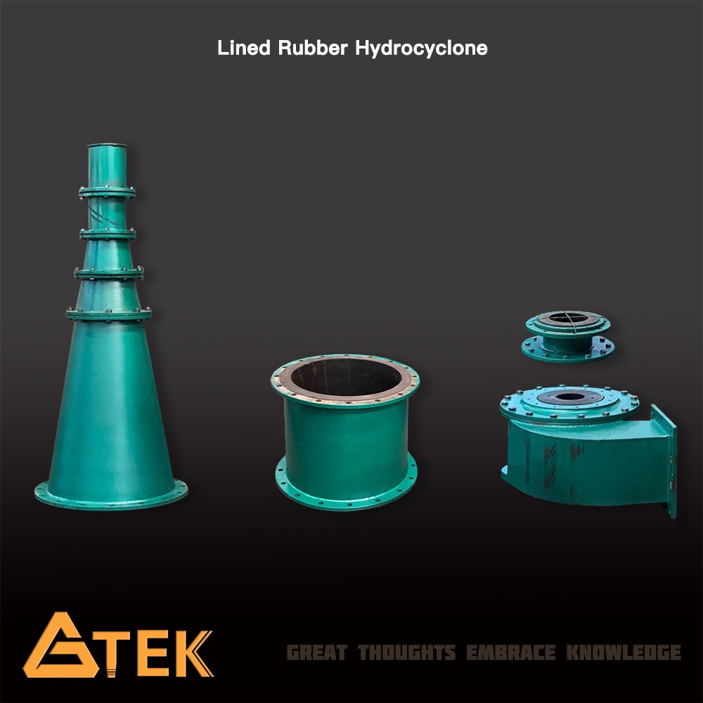
Rubber lined hydrocyclone is the most commonly used type of hydrocyclone, GTEK offers the most wear resistant rubber liner manufactured from superior natural rubber.
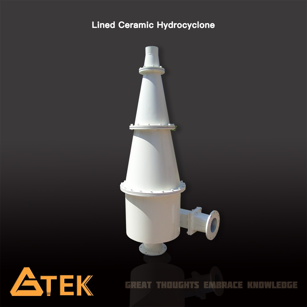
GTEK ceramic lined hydrocyclones are specifically designed for highly abrasive processes where the chemistry is not suitable for rubber liners. GTEK ceramic hydrocyclone can be used for classification in mineral processing and has proven to be a very economical means of classification, especially in closed circuit grinding operation. GTEK ceramic hydrocyclone be applied to dewatering and desliming mineral sands, bauxite ore, phosphate rock, concrete sands, and coal washery fines in mineral processing circuit.
")
")
Working Principle
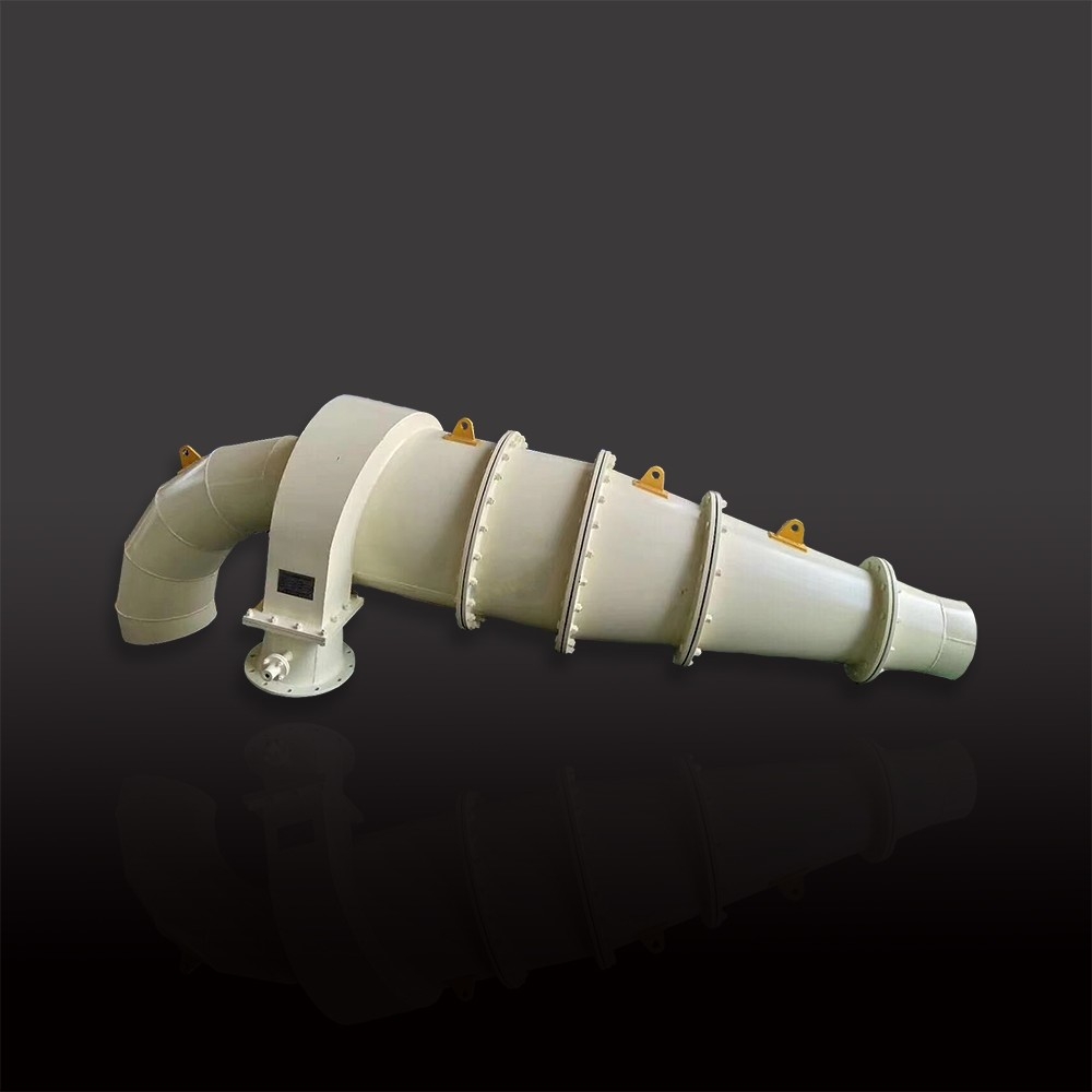
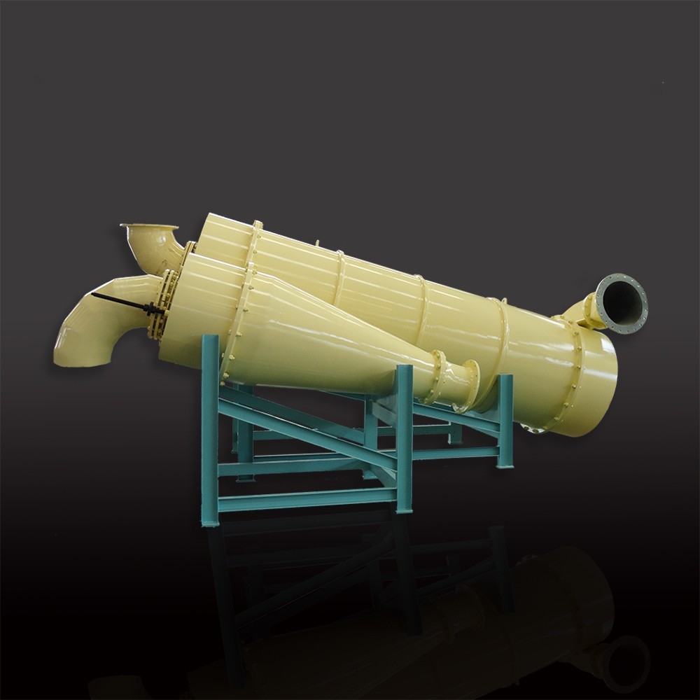
During operation, the slurry feed enters the cyclone under pressure through the feed pipe into the top of the cylindrical feed chamber. As the feed enters the chamber, as result of the high centrifugal forces, the particles migrate downward in a spiral pattern through the cylindrical section and into the conical section. At this point the finer particles migrate toward the center and spiral upward and out through the vortex finder, discharging through the overflow pipe. The coarse particles remain in a downward spiral path along the walls of the conical section and gradually exit through the apex orifice.
")
Features
1. Wear resistance rubber liner manufactured from superior natural rubber;
2.Wear resistance liner manufactured from high alumina oxide or reaction boned silicon carbide for some models
3. Delivery maximum efficiency, maximum capacity due to scrolled evolute inlet design
4. Lower cyclone operating costs,longer wear Life;
5. Maximum separation efficiency, maximum hydraulic capacity;
6. Easier installation and maintenance;
7. Ceramics are available for lower cones and spigots.
Model | Interior Dia (mm) | Cone Angle | Overflow Diameter (mm) | Feed Size (mm) | Inlet Pressure (Mpa) | Process Capacity (m3/h) | Range (um) | Dimensions (L*W*H)(mm) | ||
FX660 | 660 | 20 | 180-240 | 16 | 0.03-0.2 | 250-350 | 74-220 | 1250 | 890 | 2650 |
FX500 | 500 | 20 | 130-200 | 10 | 0.03-0.3 | 140-220 | 74-200 | 850 | 790 | 2050 |
15 | 74-150 | 850 | 790 | 2380 | ||||||
FX350 | 350 | 10 | 80-120 | 6 | 0.04-0.3 | 60-100 | 50-150 | 775 | 605 | 1765 |
15 | 50-120 | 775 | 605 | 2115 | ||||||
FX300 | 300 | 20 | 65-115 | 5 | 0.04-0.3 | 45-85 | 50-150 | 665 | 585 | 1310 |
15 | 40-100 | 665 | 585 | 1505 | ||||||
FX250 | 250 | 20 | 60-100 | 3 | 0.06-0.35 | 40-60 | 40-100 | 540 | 480 | 1180 |
15 | 40-100 | 540 | 480 | 1220 | ||||||
10 | 30-100 | 540 | 480 | 1380 | ||||||
FX200 | 200 | 20 |
40-65 | 2 | 0.06-0.35 | 25-40 | 40-100 | 435 | 360 | 1050 |
15 | 30-100 | 435 | 360 | 1115 | ||||||
10 | 30-100 | 435 | 360 | 1205 | ||||||
FX150 | 150 | 20 | 30-45 | 1.5 | 0.06-0.35 | 11-20 | 30-74 | 280 | 295 | 690 |
15 | 30-74 | 280 | 295 | 900 | ||||||
8 | 30-74 | 280 | 295 | 1270 | ||||||
FX125 | 125 | 17 | 25-40 | 1 | 0.06-0.35 | 8-15 | 20-100 | 210 | 185 | 620 |
8 | 20-74 | 250 | 240 | 985 | ||||||
FX100 | 100 | 20 | 20-40 | 1 | 0.06-0.35 | 5-12 | 20-100 | 260 | 210 | 525 |
15 | 20-100 | 268 | 215 | 720 | ||||||
8 | 20-100 | 268 | 215 | 1000 | ||||||
FX75 | 75 | 15 | 15-22 | 0.6 | 0.1-0.4 | 2-5 | 20-74 | 240 | 230 | 465 |
6 | 5-40 | 240 | 230 | 800 | ||||||
FX50 | 50 | 15 | 11-16 | 0.3 | 0.1-0.4 | 1-2 | 10-74 | 160 | 155 | 350 |
6 | 5-30 | 160 | 155 | 590 | ||||||