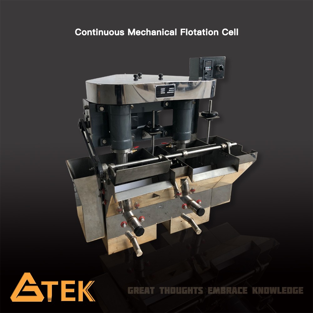
Lab Continuous Flotation Machine
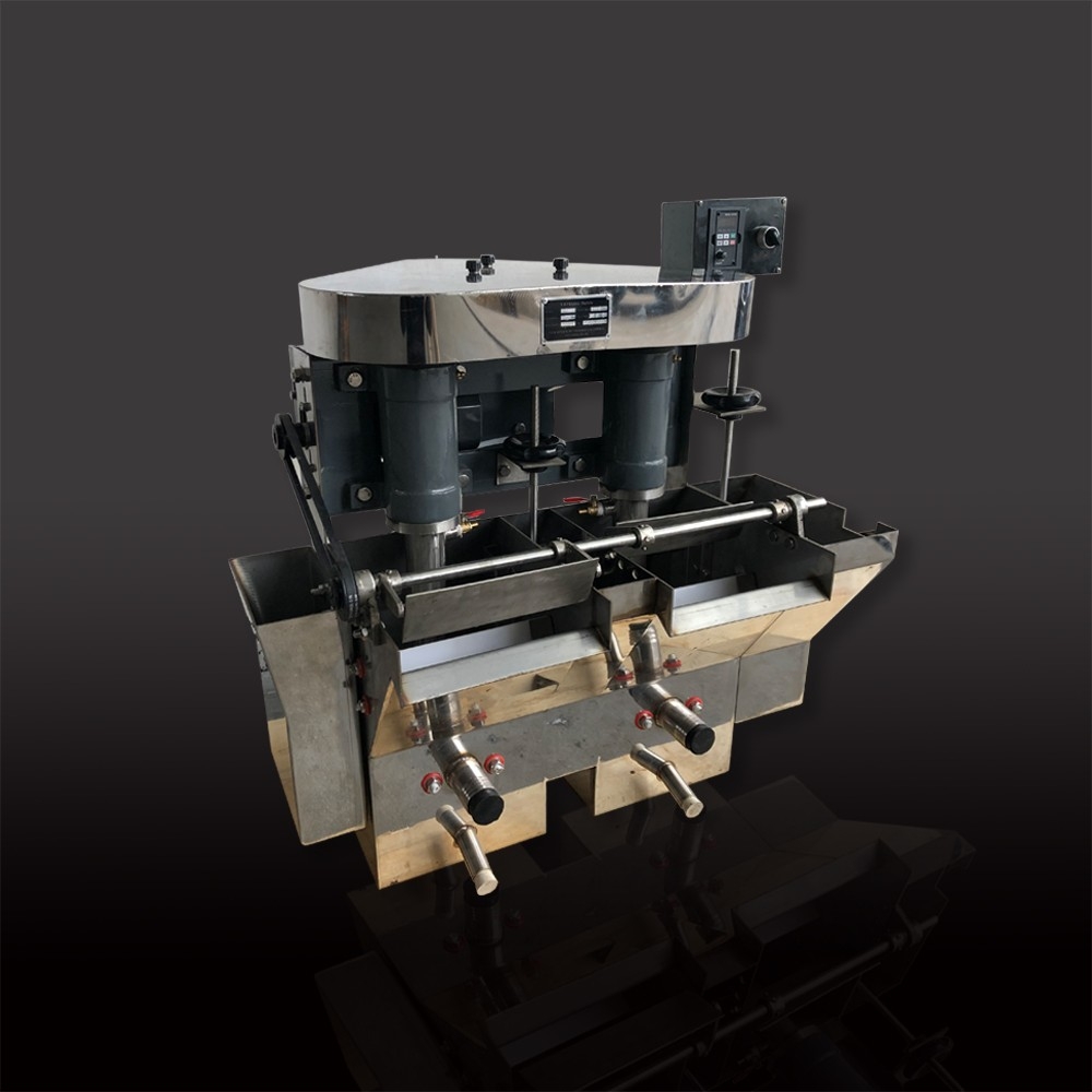
FX mechanical agitated Continuous Flotation Machine is suitable for continuous flotation test or semi-industrial production test of a small amount of minerals in the laboratory by flotation method.
Description
FX mechanical agitated Continuous Flotation Machine is suitable for continuous flotation test or semi-industrial production test of a small amount of minerals in the laboratory by flotation method. It is made up of several units and the number of cells is even. Left feed configuration or right feed configuration is available upon request.
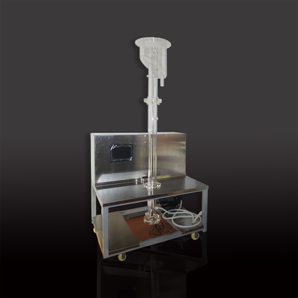
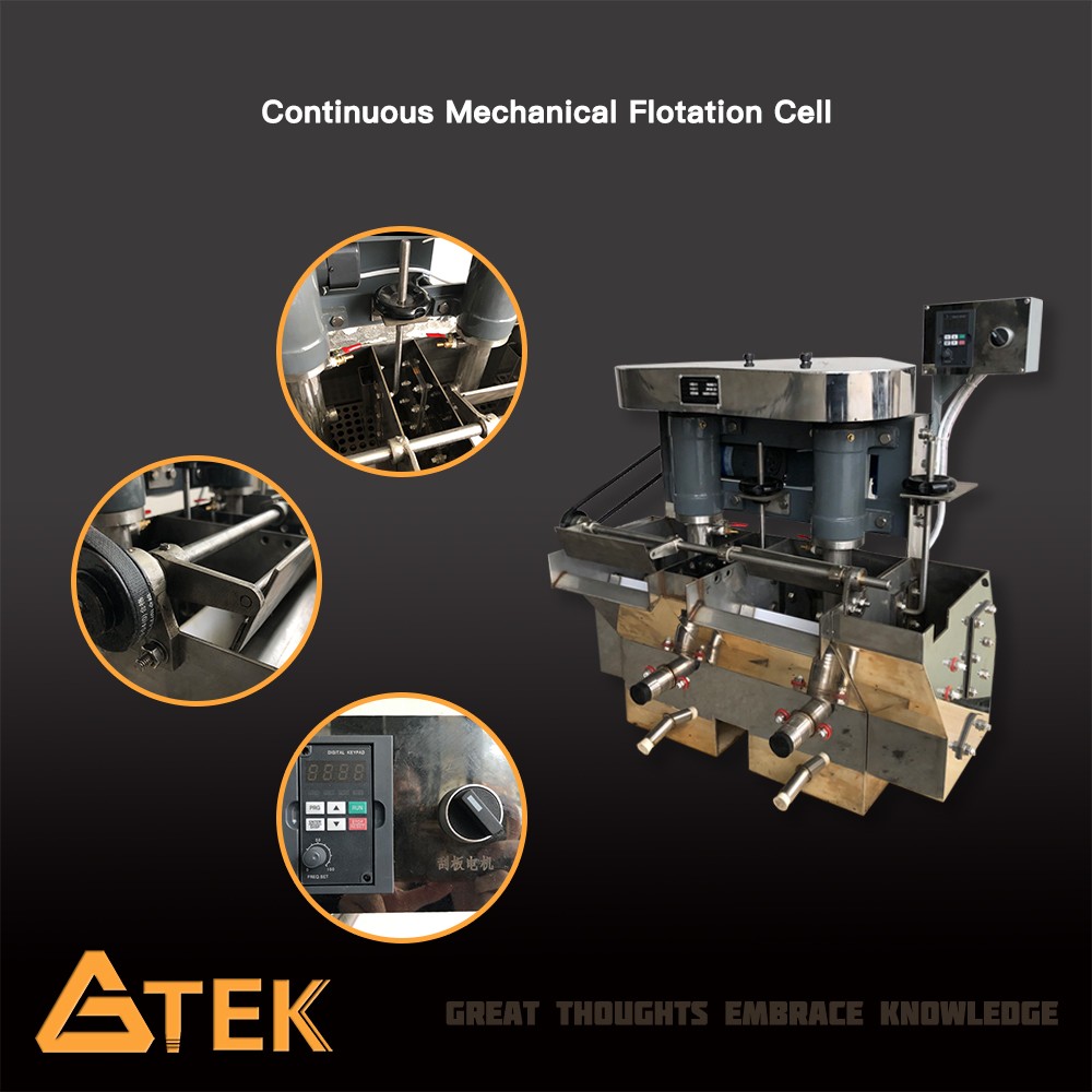
Removeable Turbulence Plate and Independent Bottom
")
How does the Turbulence affect flotation performance ?
It is known that turbulence plays an important part in the operation of a flotation cell. Rotational speed and thus intensity of turbulence has a strong influence on the recovery and grade of concentrate of single cells and cell banks. According to a conference paper:"A review of turbulence measurement techniques for flotation".We know that turbulence is one of the key parameters determining flotation performance.It affects three mian processes: suspension of particles, air dispersion and particle-bubble collision.
Working Principle
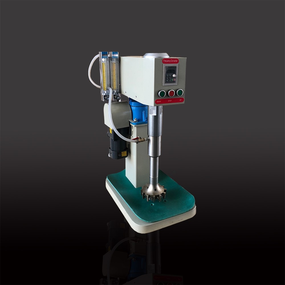
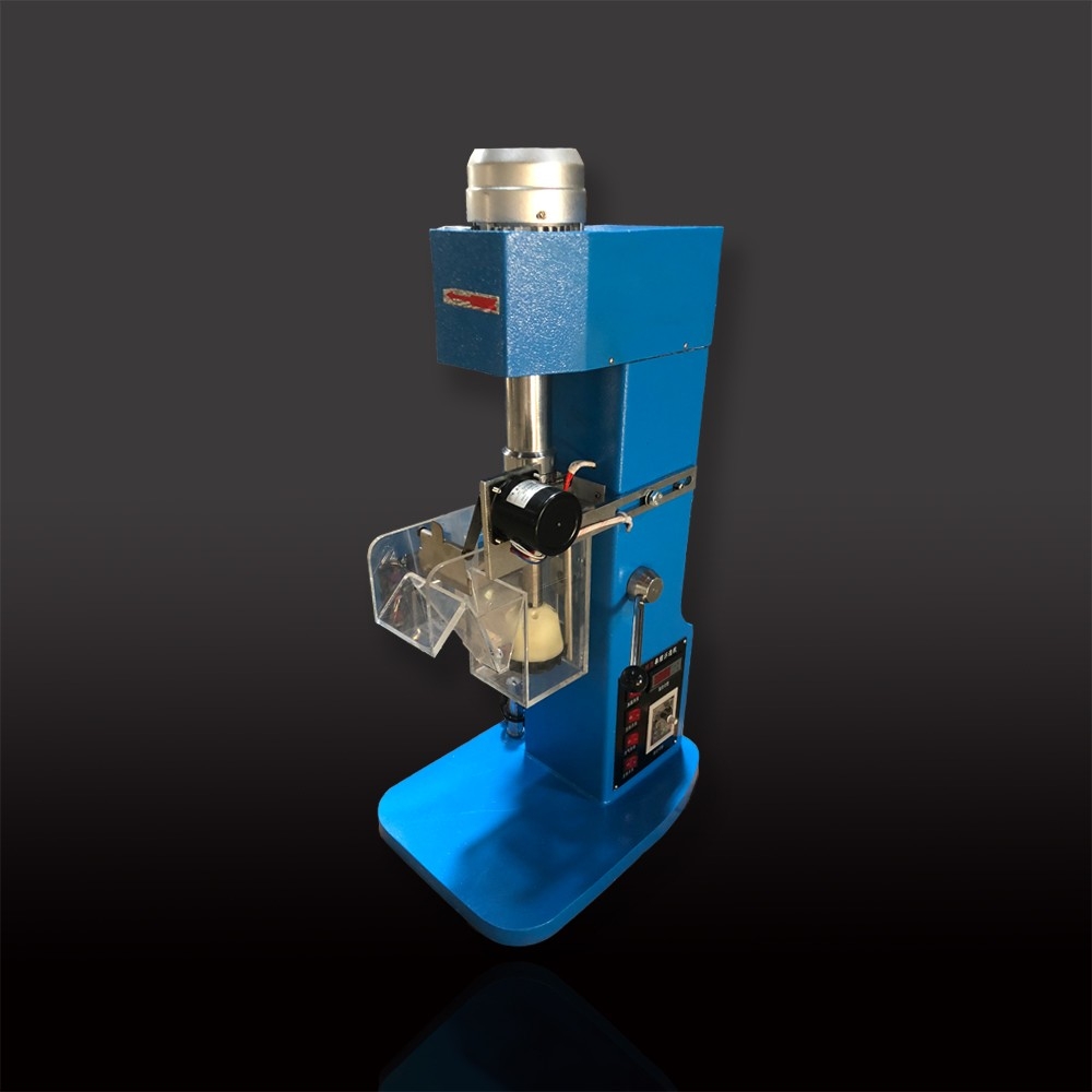
FX Flotation Machine is a kind of impeller mechanical flotation machine which mainly consist of cells, the impeller system, mainshaft system and scarping divce.
1. To adjust the level of slurry in the cell and the thickness of the scraped froth layer, use wall plates of the two cells to make intermediary cell, install slurry level regulator, and mount orifice plate onto the cover in the cell to avoid negative effects on the froth zone exerted by the chaotic motion of slurry, as well as to avoid the gangue from being taken into the concentrate by the machine.
Lining plates are installed at the cell so that the bottom of the cell will not be abraded. The lining plate can be replaced. On the outside of the cell bottom is a discharge mouth, which is used to discharge water during its cleaning.
The slurry flows through the overflow mouth of wall panel into the intermediary cell and tail cell. It flows to the lower part of the intermediary cell and the duct covered by the lower part of the cell wall and then to the next cell. In this way, it can continue to flow through all the cells of flotation machine. It flows from the feed cell and is discharged from the discharge mouth of the tail cell. The front and back of the lower part of the cell is installed feeding mouth, to make it easy to change the process flow.
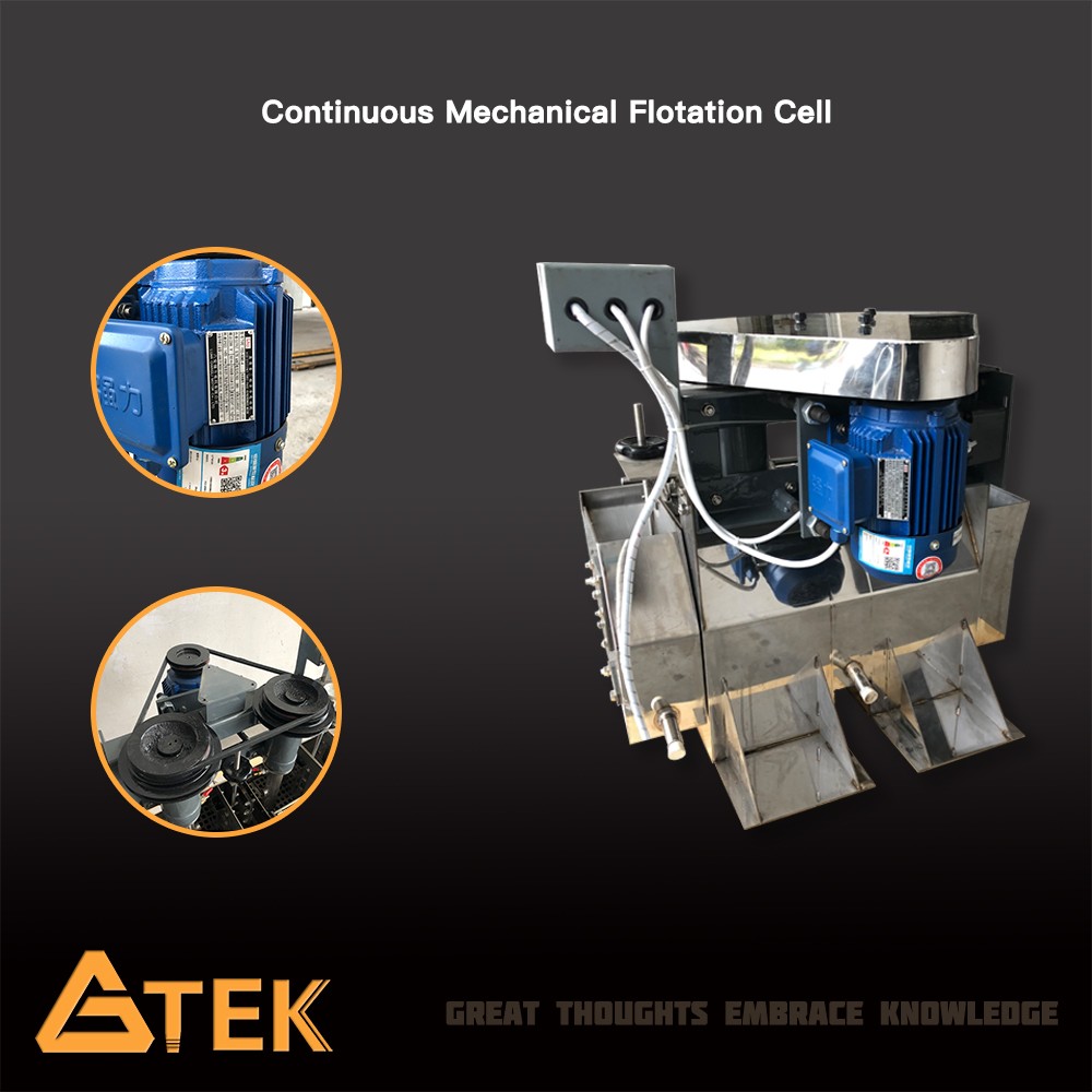
2. The impeller system is a disk impeller which is installed in the center of the cell in the flotation machine and whose blades are radially arranged. It is fixed onto the lower end of the impeller shaft and revolves around the vertical shaft pipe. The upper end of the pipe lies above the pulp stone and the froth layer while its lower end is supported on the cover. When the impeller rotates, a large amount of air can be sucked along the vertical pipe. Below the cover is fixed protective disk. The gap between the safety disk and the impeller depends on the amount of sucked air. It cannot be larger than 3mm at most. When the gap is too large, replace the abraded protective disc and make appropriate adjustment.
The holes in the vertical pipe are used to circulate slurry as well as mix the slurry and air. The rolling shaft installed inside the bearing shell above the impeller shaft rotates. The bearing shell is installed on the crossbeam and belt pulley is fixed on the top of the shaft which rotates through the V-belt when the motor is turned on. The tension of the V-belt is adjusted through the nuts.
3. Scraping device: The froth is scraped along the flotation machine through rotary scraper. The scraper is installed outside the discharge mouth of cell. At one end of the scraping shaft is installed belt pulley which rotates through the drive of worm reducer and V-belt.
Features
Model | FX2-1.5 | FX2-3 | FX2-7 | FX2-12 | FX2-24 | FX2-39 | |
Cell Volume (L) | 1.5 | 3 | 7 | 12 | 24 | 39 | |
Cell Quantity | 2 | ||||||
Impeller Diameter (mm) | Φ70 | Φ110 | Φ130 | Φ170 | Φ200 | ||
Impeller Speed (r/min) | 1400 | 1332,1600,1836 | 1050-1320 | 680-1080 | 447-787 | 809 | |
Scraper Speed (r/min) | 33 | 20,30 | 20,30 | 24 | 12,16,20 | 13,21 | |
Feeding Size (mm) | ≤0.2 | ||||||
Power (W) | 250 | 250 | 370 | 600 | 1100 | 1500 | |
External Size | Length (mm) | 378 | 500 | 623 | 740 | 924 | 1081 |
Width (mm) | 406 | 500 | 590 | 600 | 804 | 762 | |
Height (mm) | 523 | 600 | 750 | 700 | 925 | 930 | |
Weight (kg) | 25 | 40 | 55 | 85 | 260 | 280 | |